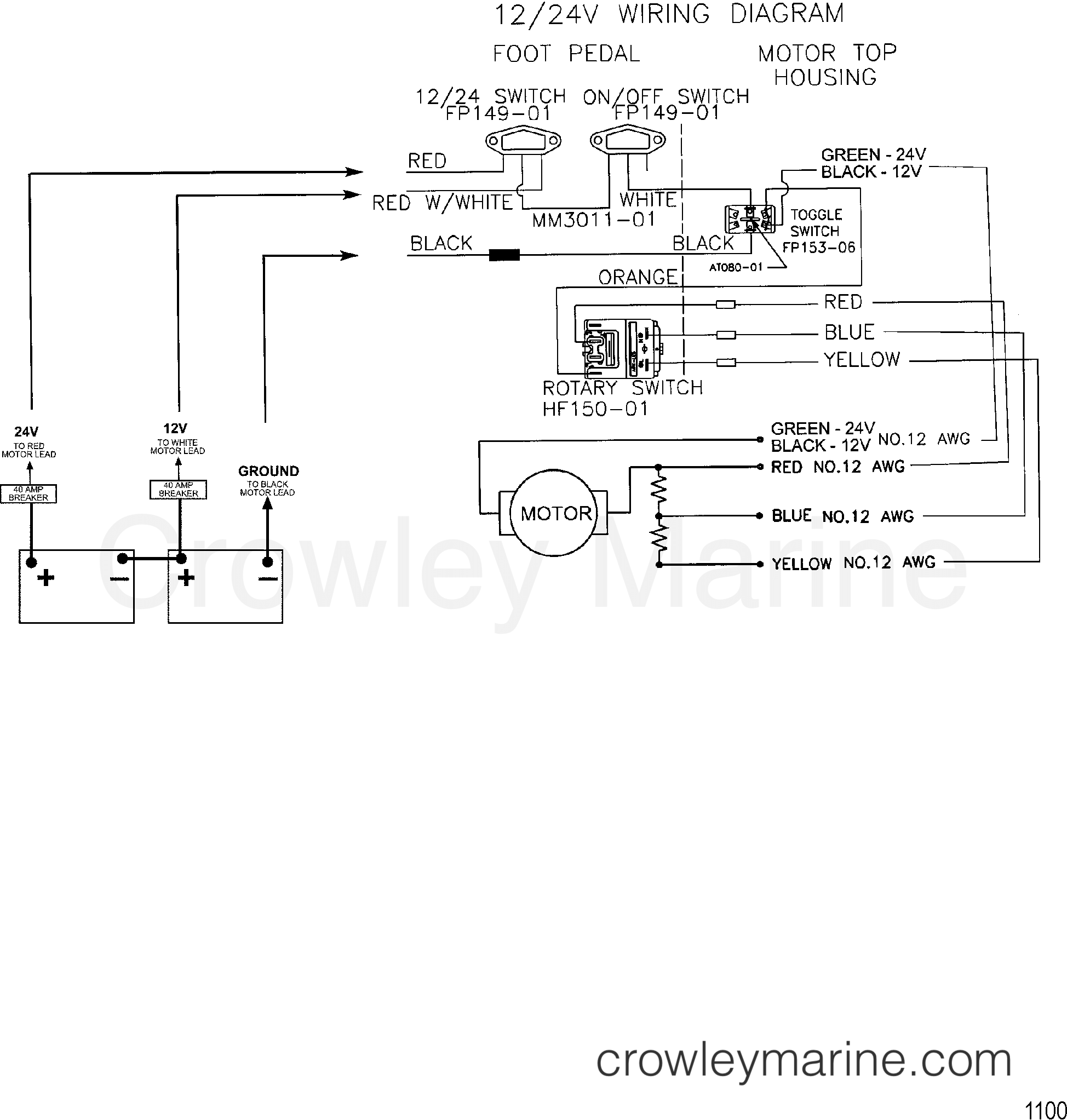
Wiring diagram 24 trolling motor volt 24v minn kota batteries system boat motorguide brute lb hooking way question wire motors Buck boost current circuit led voltage negative converter inverting output regulates constant figure Diagram volt wire motorguide model 24 volt boosting diagram
Trolling Motor Wiring and Battery Guide | Minn Kota
Wiring 24 volt trolling motor 2 battery 24 volt wiring diagram collection 24 volt battery wiring diagram
Boost volt reduces starts
Ac battery wiring diagram : parallel charging using multipleWire diagram(model 667) (24 volt) Trolling motor wiring and battery guideHow to wire batteries in series and parallel [24 & 36 volt trolling.
24 volt starter solenoid wiring diagramCharge at 24v and discharge at 12v for battery system – valuable tech notes What is the proper way of hooking up batteries for 24 volt system on myBoost converter dc 12v to 24v 12 volt to 24 volt 1a.
![[SOLVED] Charging 24V Battery with 12V Alternator and Isolator ~ Motor](https://i2.wp.com/i.stack.imgur.com/hvjuA.jpg)
Simple voltage booster circuit using transistors
24 volt minn kota wiring diagram for your needsWiring trolling volt motor diagram 24v 24 minn kota plug system battery hook minnkota electric wire batteries 12v diagrams motors Charging battery systems starting system electrical operation figure tpub️48 volt electric scooter wiring diagram free download| gmbar.co.
How to get 24v from two 12v batteriesCharge at 24v and discharge at 12v for battery system – valuable tech notes Wiring controllers24v booster battery recovery system switch overlanding hubb share.

24v battery booster recovery system's overlanding
24 and 36-volt wiring diagrams – trollingmotors.netStarting system wiring diagram 24 volt with negative battery relay 24 volt boost converter design[solved] charging 24v battery with 12v alternator and isolator ~ motor.
Charging systemUsing a 24 volt alternator for wind generator Booster voltage transistors circuits explanationSimple way to boost a 24v system.

Inverting buck-boost converter regulates led current
24v wiring diagram for trolling motors .
.